martes, 29 de noviembre de 2011

JAVA Y ARDUINO

PASO 1: Ejecuta el programa arduino.
Paso 2: ya con el arduino ejecutándose, ejecuta el programa Main.java
el resultado se imprime en la tela del programa java:


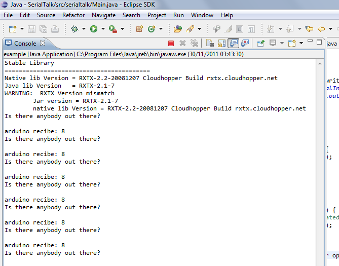
el Programa usado en arduino envia una frase y java lo lee y lo imprime.
java tambien le envia un caracter: 8, arduino lo recibe y se lo vuelve a enviar.
programa Arduino:
////////////////////////////////////////////////////////
///////////////////////////////////////////////////////


int incomingByte = 0;
void setup(){
  Serial.begin(9600);
}

void loop(){
  Serial.println("Is there anybody out there? \n");
  delay(1000);
  if (Serial.available() > 0)

   {
// read the incoming byte:
incomingByte = Serial.read();
     
// say what you got:
Serial.print("arduino recibe: ");
Serial.println(incomingByte, DEC);
}}


/////////////////////////////////////////////////////////////////////
/////////////////////////////////////////////////////////////////////

/*Programa en: */ JAVA usado para leer escribir en el arduino


package serialtalk;

import gnu.io.CommPortIdentifier;
import gnu.io.NoSuchPortException;
import gnu.io.SerialPort;

import java.io.IOException;
import java.io.InputStream;
import java.io.OutputStream;


public class Main {
    static InputStream serialInt;
    static OutputStream serialOut;


    public static void main(String[] args) throws Exception{
     
 
    try {
CommPortIdentifier portId = null;
try {
portId = CommPortIdentifier.getPortIdentifier("COM3");
} catch (NoSuchPortException npe) {

}
SerialPort port = (SerialPort)portId.open("Título comunicação serial", 9600);
serialOut = port.getOutputStream();
serialInt = port.getInputStream();
port.setSerialPortParams(9600,
SerialPort.DATABITS_8,
SerialPort.STOPBITS_1,
SerialPort.PARITY_NONE);


/*  */

while(true){
   serialOut.write(8);
           while(serialInt.available()>0) {
               System.out.print((char)(serialInt.read()));
           }
       }

/**/
   

} catch (Exception e) {
e.printStackTrace();
}
}

public void close(){
try {
serialOut.close();
} catch (IOException e) {
// TODO Auto-generated catch block
e.printStackTrace();
}
}

public void enviaDados(char opcao){
try {
serialOut.write(opcao);
} catch (IOException e) {
e.printStackTrace();
}
}


    }


domingo, 27 de noviembre de 2011

Circuito Emisor/ Receptor Infrarrojo y Arduino

Aqui el circuito del transmisor receptor infrarrojo y la entrada al Arduino:
Para el proyecto use los sensores: 

Infrared Emitters and Detectors de sparkfun.

el que tiene un color rosado es el receptor:
El que es incoloro es el emisor:


// Pequeño programa para detectar si hay un obstáculo entre el transmisor y receptor infrarrojo.
// set pin numbers:
const int buttonPin = 12;     // Pin de entrada
const int ledPin =  13;      // the number of the LED pin

// variables will change:
int buttonState = 0;         // variable for reading the pushbutton status

void setup() {
  // initialize the LED pin as an output:
  pinMode(ledPin, OUTPUT);    
  // initialize the pushbutton pin as an input:
  pinMode(buttonPin, INPUT);  
}

void loop(){
  // read the state of the pushbutton value:
  buttonState = digitalRead(buttonPin);

  // check if the pushbutton is pressed.
  // if it is, the buttonState is HIGH:
  if (buttonState == HIGH) {  
    // led se prende cuando hay un obstaculo entre el transmisor   y receptor
    digitalWrite(ledPin, HIGH);
  }
  else {
    // led se apaga cuando no se obstruye el paso entre el transmisor y el receptor
    digitalWrite(ledPin, LOW);
  }
}

viernes, 23 de septiembre de 2011

Sensor de Temperatura y Humedad SHT15 usando Arduino


la conexión del sensor con el Arduino UNO:


Aquí el código fuente que me funciono en mi proyecto:


///////////////////////////////////////////////////////////////////////////////////////////
int gTempCmd  = 0b00000011;
int gHumidCmd = 0b00000101;

int shiftIn(int dataPin, int clockPin, int numBits)
{
   int ret = 0;
   int i;

   for (i=0; i<numBits; ++i)
   {
      digitalWrite(clockPin, HIGH);
      delay(10);  // I don't know why I need this, but without it I don't get my 8 lsb of temp
      ret = ret*2 + digitalRead(dataPin);
      digitalWrite(clockPin, LOW);
   }

   return(ret);
}

void sendCommandSHT(int command, int dataPin, int clockPin)
{
  int ack;


  pinMode(dataPin, OUTPUT);
  pinMode(clockPin, OUTPUT);
  digitalWrite(dataPin, HIGH);// protocolo para la transmision
  digitalWrite(clockPin, HIGH);
  digitalWrite(dataPin, LOW);
  digitalWrite(clockPin, LOW);
  digitalWrite(clockPin, HIGH);
  digitalWrite(dataPin, HIGH);
  digitalWrite(clockPin, LOW);
         
  // The command (3 msb are address and must be 000, and last 5 bits are command)
  shiftOut(dataPin, clockPin, MSBFIRST, command);

  // Verify we get the coorect ack
  digitalWrite(clockPin, HIGH);
  pinMode(dataPin, INPUT);
  ack = digitalRead(dataPin);
  if (ack != LOW)
    Serial.println("Ack Error 0");
  digitalWrite(clockPin, LOW);
  ack = digitalRead(dataPin);
  if (ack != HIGH)
     Serial.println("Ack Error 1");
}

void waitForResultSHT(int dataPin)
{
  int i;
  int ack;

  pinMode(dataPin, INPUT);

  for(i= 0; i < 100; ++i)
  {
    delay(10);
    ack = digitalRead(dataPin);

    if (ack == LOW)
      break;
  }

  if (ack == HIGH)
    Serial.println("Ack Error 2");
}

int getData16SHT(int dataPin, int clockPin)
{
  int val;

  // Get the most significant bits
  pinMode(dataPin, INPUT);
  pinMode(clockPin, OUTPUT);
  val = shiftIn(dataPin, clockPin, 8);
  val *= 256;

  // Send the required ack
  pinMode(dataPin, OUTPUT);
  digitalWrite(dataPin, HIGH);
  digitalWrite(dataPin, LOW);
  digitalWrite(clockPin, HIGH);
  digitalWrite(clockPin, LOW);
         
  // Get the lest significant bits
  pinMode(dataPin, INPUT);
  val |= shiftIn(dataPin, clockPin, 8);

  return val;
}

void skipCrcSHT(int dataPin, int clockPin)
{
  // Skip acknowledge to end trans (no CRC)
  pinMode(dataPin, OUTPUT);
  pinMode(clockPin, OUTPUT);

  digitalWrite(dataPin, HIGH);
  digitalWrite(clockPin, HIGH);
  digitalWrite(clockPin, LOW);
}

void setup()
{
   Serial.begin(9600); // open serial
}

void loop()
{
  int theDataPin  = 10;
  int theClockPin = 11;
  int ack;


           int val;
           int temperatura;
           int humedad;
         
           sendCommandSHT(gTempCmd, theDataPin, theClockPin);
           waitForResultSHT(theDataPin);
           val = getData16SHT(theDataPin, theClockPin);
           skipCrcSHT(theDataPin, theClockPin);
           Serial.print("Temperatura:");
           //Serial.print(val, HEX);
           temperatura = -40.1 + 0.01 * (float)val;
           Serial.print("  ");
           Serial.println(temperatura, DEC);      
       
     
           //lee el pin Data, con el comando de humedad y imprime el resultado
       
         
           sendCommandSHT(gHumidCmd, theDataPin, theClockPin);
           waitForResultSHT(theDataPin);
           val = getData16SHT(theDataPin, theClockPin);
           skipCrcSHT(theDataPin, theClockPin);
           Serial.print("umidade:");
           //Serial.print(val, HEX);
       
           humedad = -2.0468 + 0.0367 * val + -0.0000015955 * val * val;
           Serial.print("  ");
           Serial.println(humedad, DEC);
     
           delay(1000); //demora 1s antes de leer otra vez la temperatura y humedad
}
///////////////////////////////////////////////////////////////////////////////////////////////////////////////////////////////////

jueves, 14 de julio de 2011

Arduino y teclado 3x4

  Para este proyecto use el   teclado de sparkfun de 12 teclas (0-9, *, # ) este teclado tiene el siguiente diagrama:

como se ve en la figura, el teclado cuenta con 7 pines de control. por ejemplo cuando aprietas la tecla numero 1 se conectan los pines 2 y 3, para la tecla 5 se conectan los pines 7 y 1.

después de comprobar cuales son los pines correspondientes a las filas (2,7,6,4) y columnas (3,1,5) del teclado matricial, definimos a que entradas del arduino van a ir conectado. en nuestro caso los defino de la siguiente forma:

pin del tecla(1, 2, 3, 4, 5, 6, 7) CONECTADOS RESPECTIVAMENTE A
pin del arduino(7D, 5D, 8D, 2D, 6D, 3D, 4D).


A la vez se conectaran resistencias de un 10K ohm a los pines correspondientes a las filas del teclado y el otro extremo de las resistencias se conectaran a 5v como se ve en la figura:
Código
El programa consiste  en visualizar en el monitor serial del arduino, cada tecla presionada del teclado matricial.
Antes de ejecutar el programa, baja el keypad.zip , descomprime y coloca la carpeta en "hardware\libraries\".
Aquí el programa que use:


//////////////////////////////////////////////////////////////////
//©2011
//Released under the MIT License - Please reuse change and share
//Reads the keys pressed on a keypad
//Thanks to Alexander Brevig for his original keypad code.
/////////////////////////////////////////////////////////////////

#include <Keypad.h>  //needs to be in the library folder (Arduino/Libraries)

const byte ROWS = 4; //four rows
const byte COLS = 3; //three columns
char keys[ROWS][COLS] = {
  {'1','2','3'},
  {'4','5','6'},
  {'7','8','9'},
  {'*','0','#'}
};
byte rowPins[ROWS] = {5, 4, 3, 2}; //connect to the row pinouts of the keypad
byte colPins[COLS] = {8, 7, 6}; //connect to the column pinouts of the keypad

Keypad keypad = Keypad( makeKeymap(keys), rowPins, colPins, ROWS, COLS );

void setup(){
  Serial.begin(9600); //initialise the serial port (9600 baud)
}
 
void loop(){
  char key = keypad.getKey();
 
  if (key != NO_KEY){
    Serial.println(key); //print to serial the key that has been pressed
  }
}